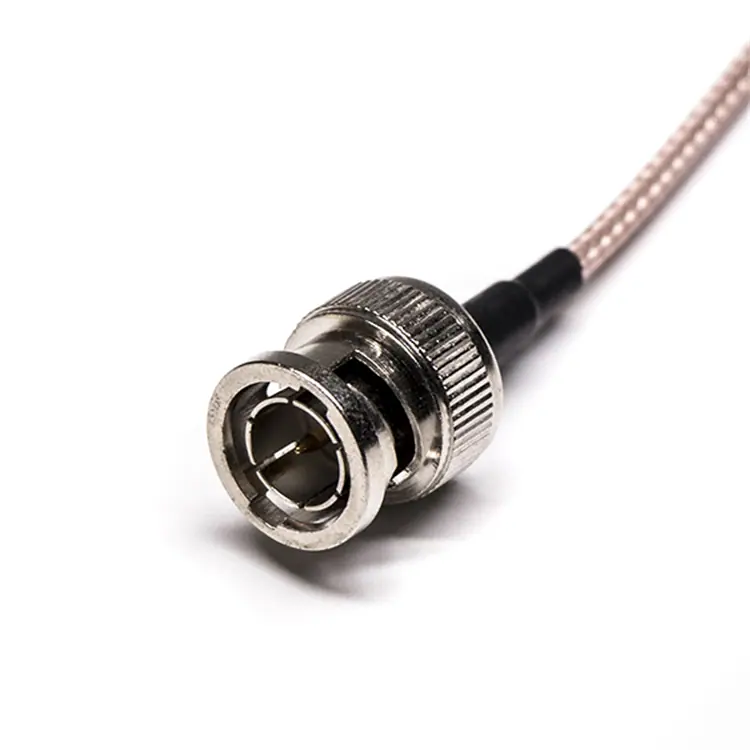
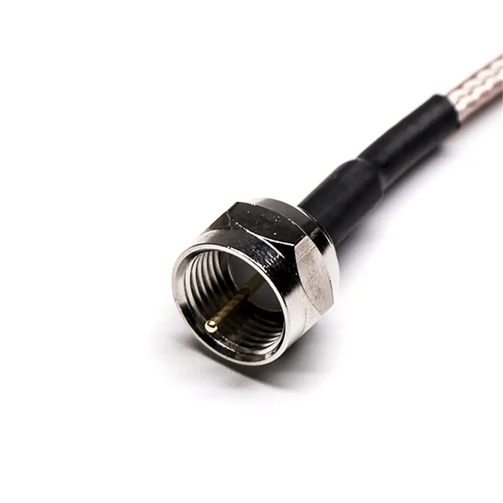
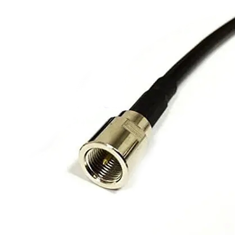
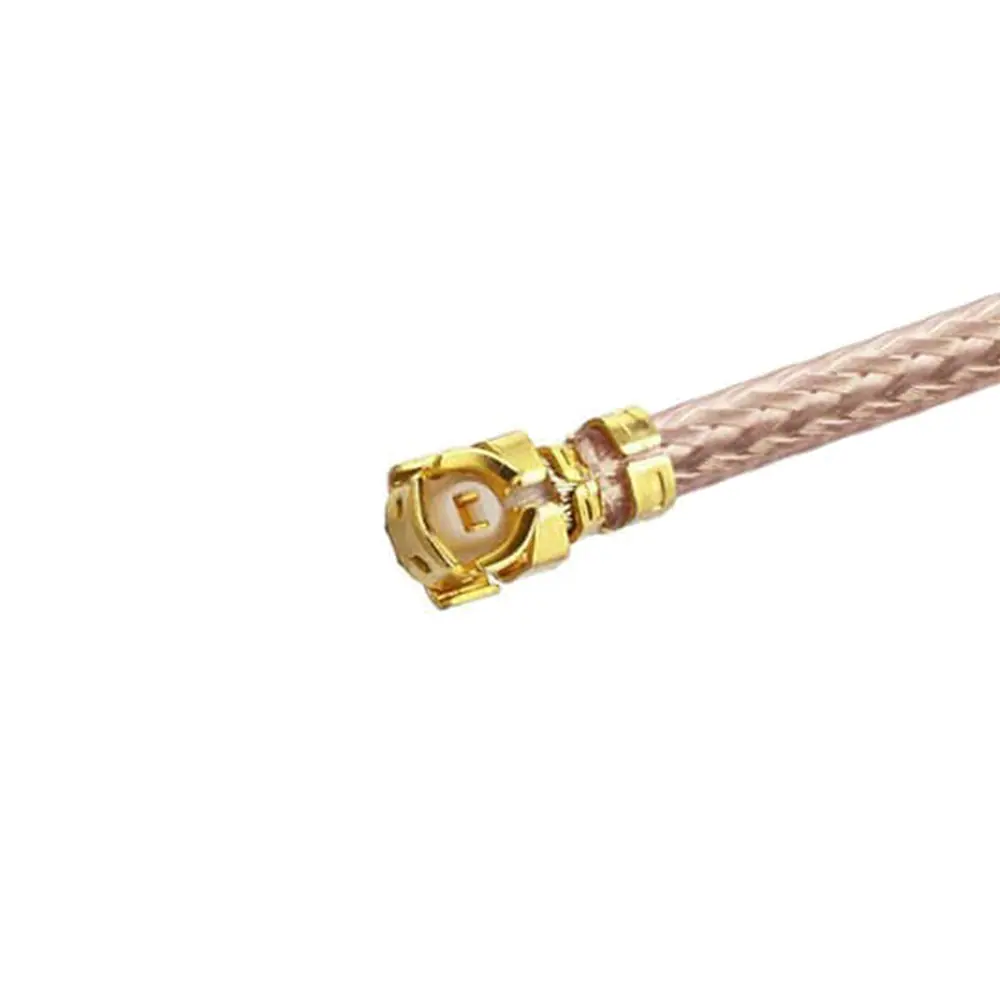
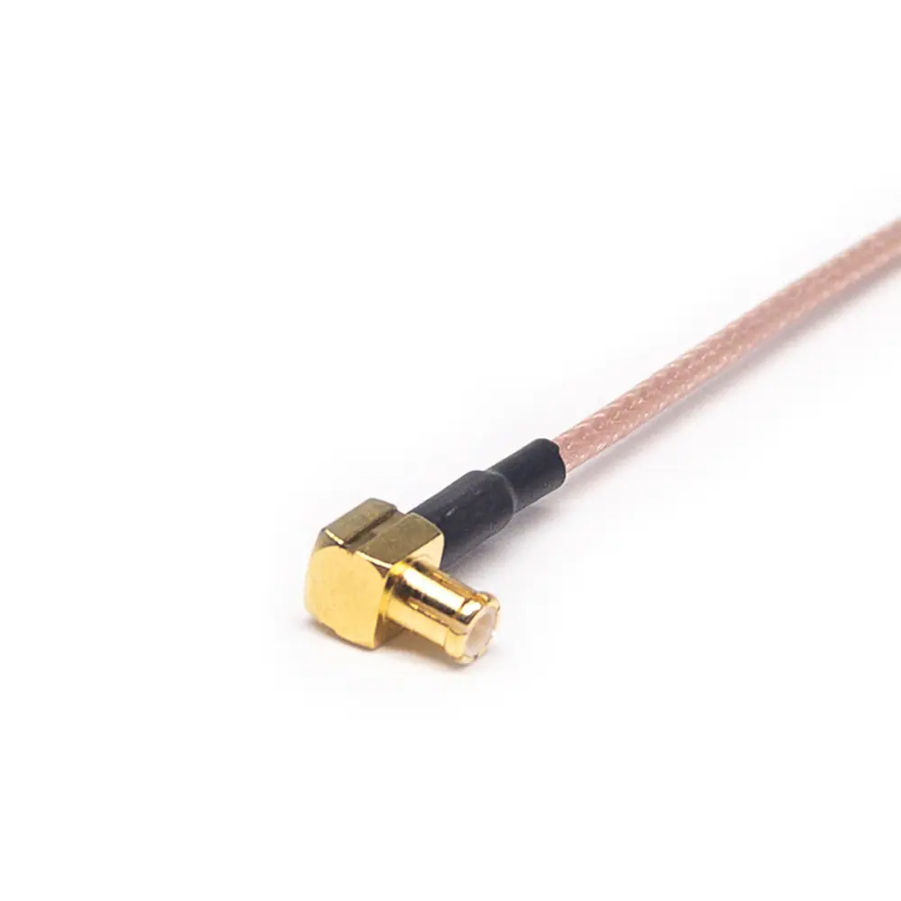
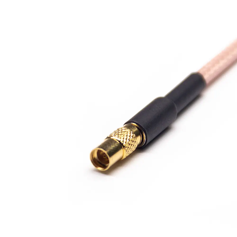
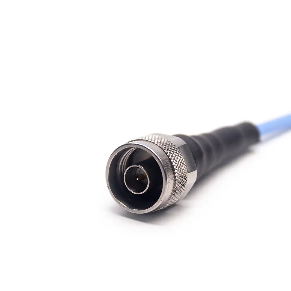
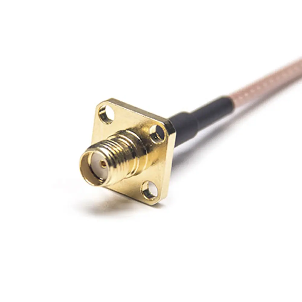
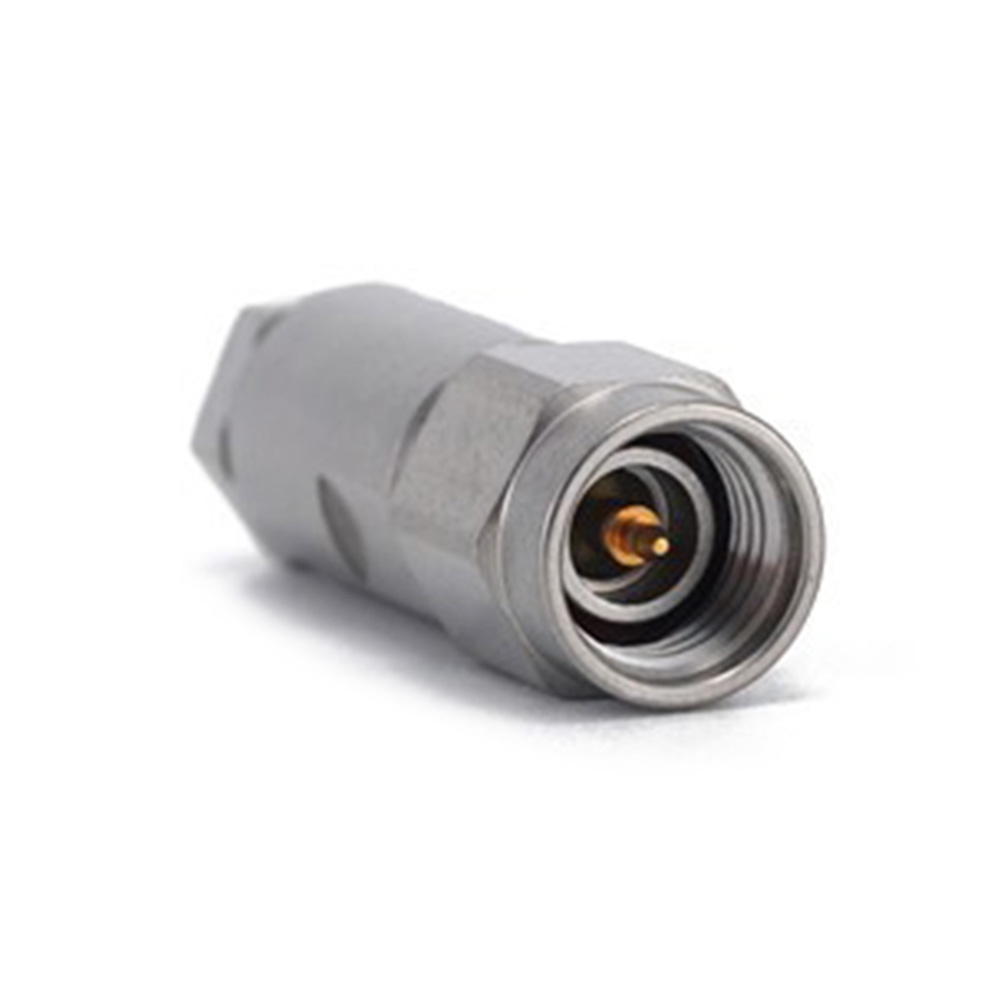
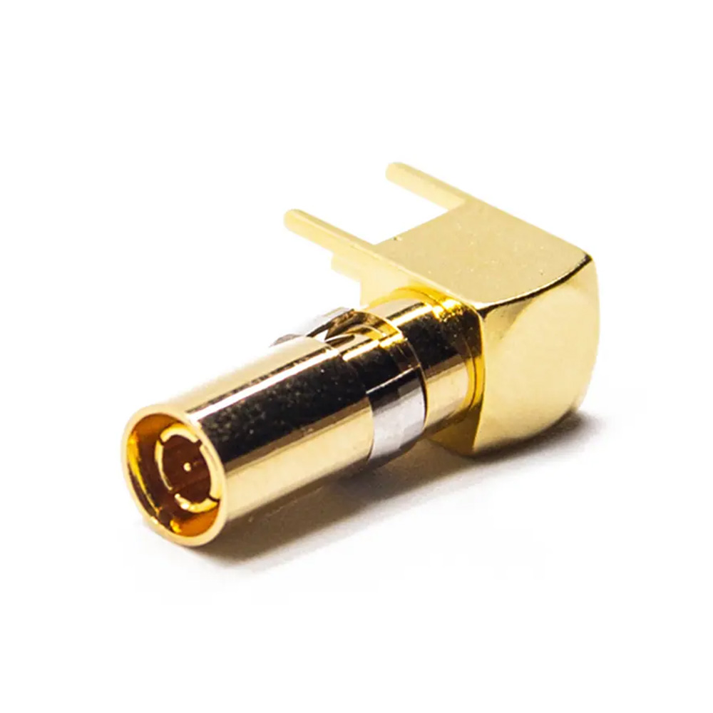
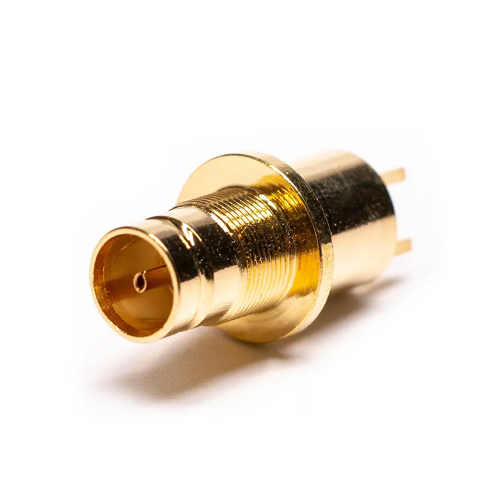
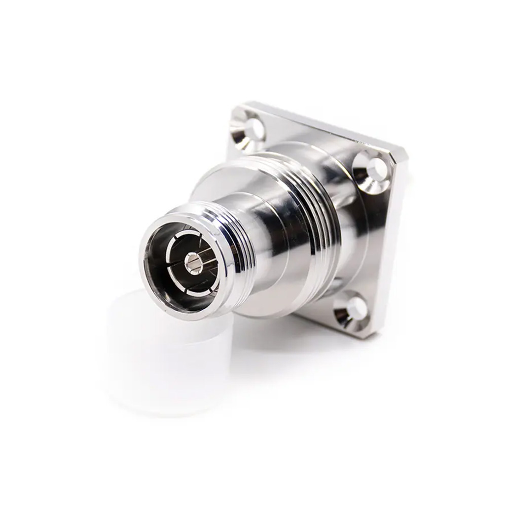
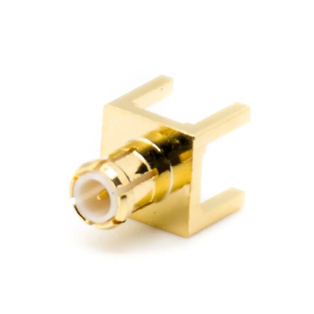
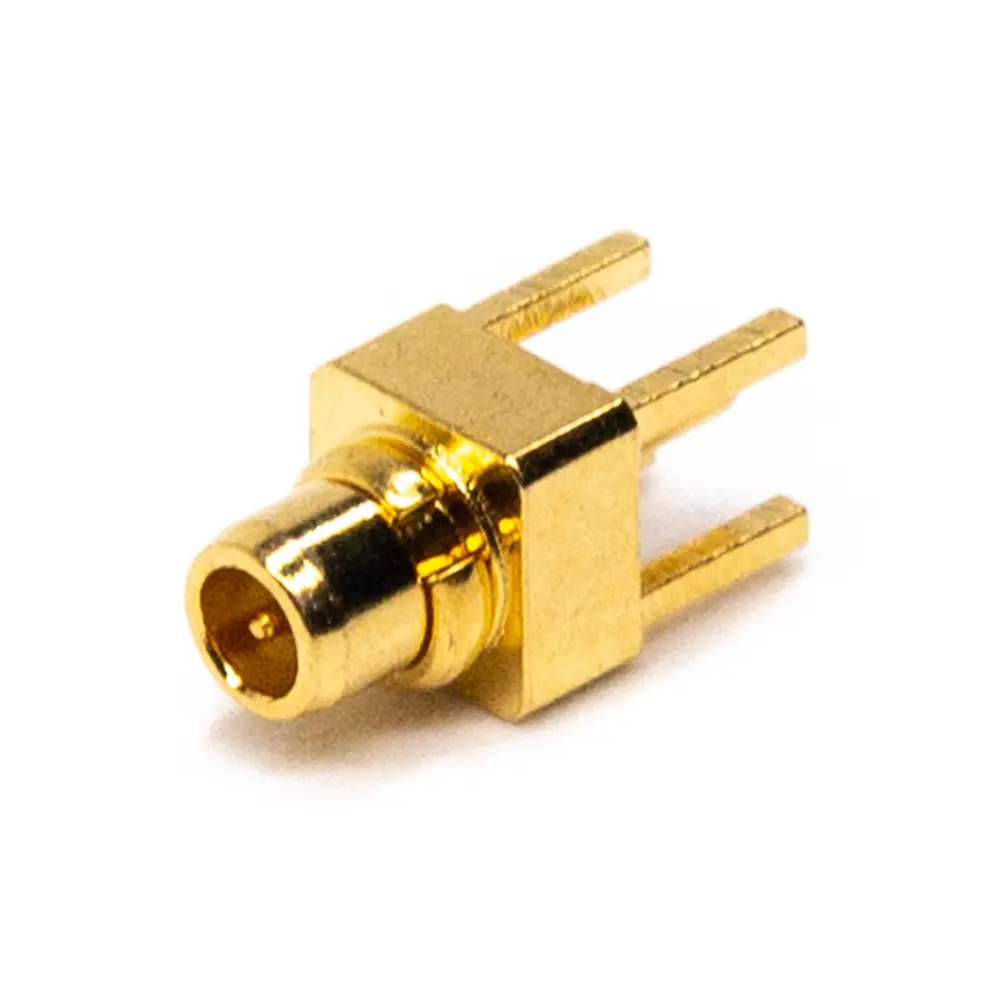
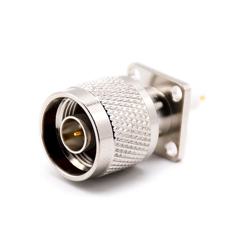
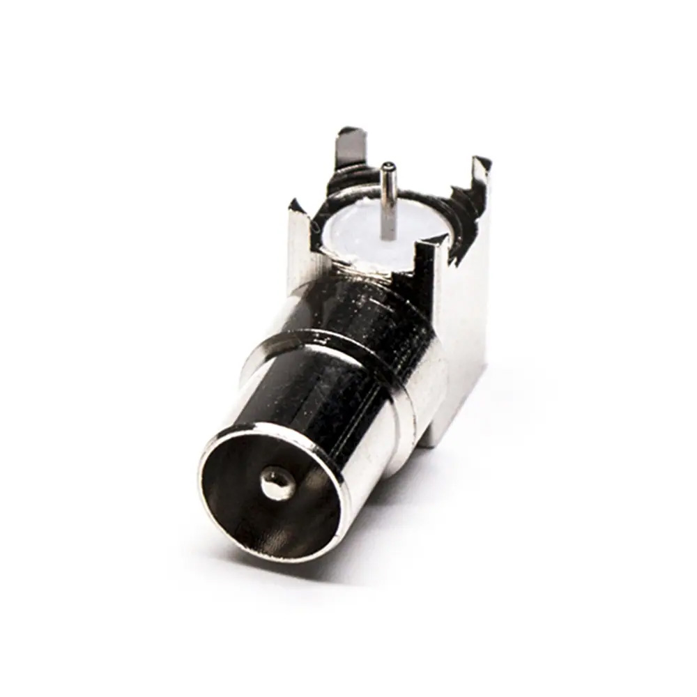
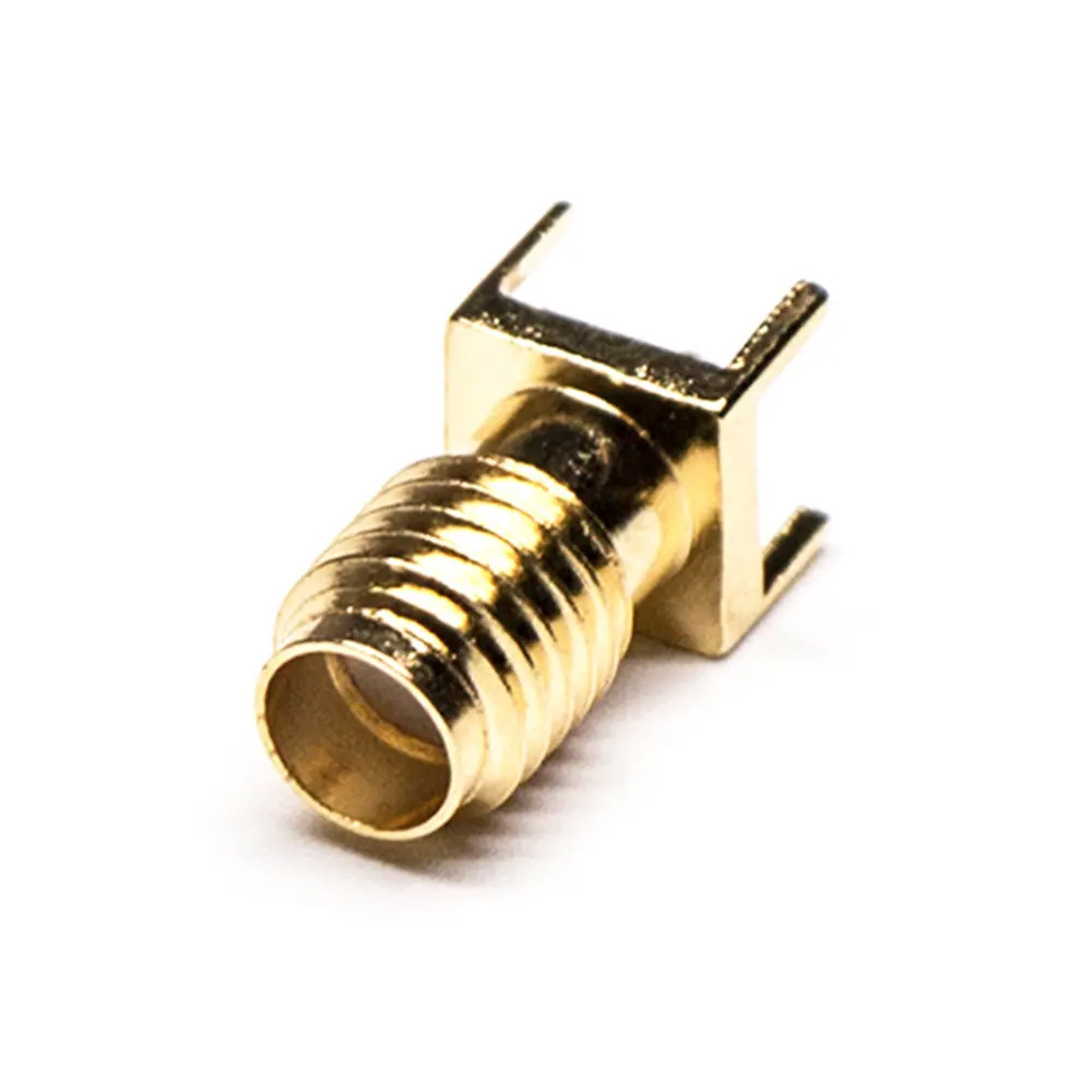
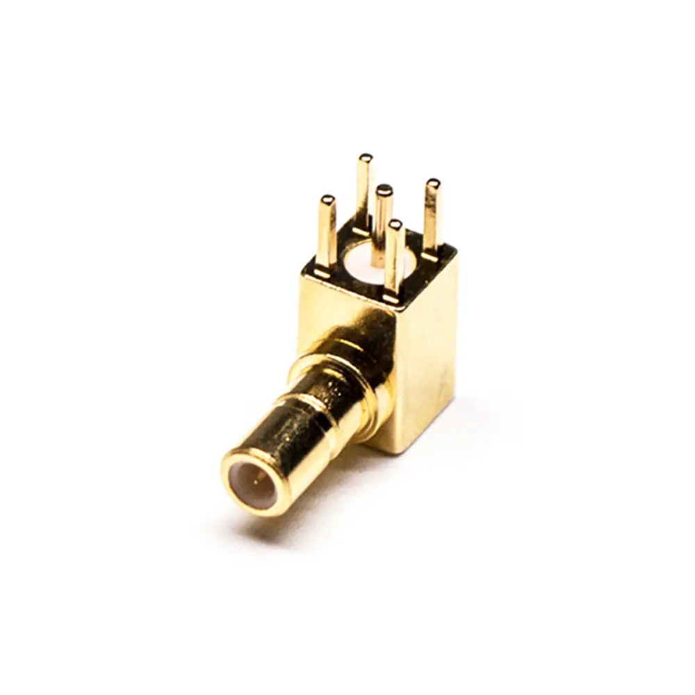
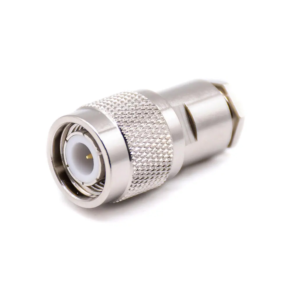
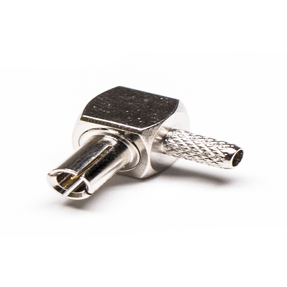
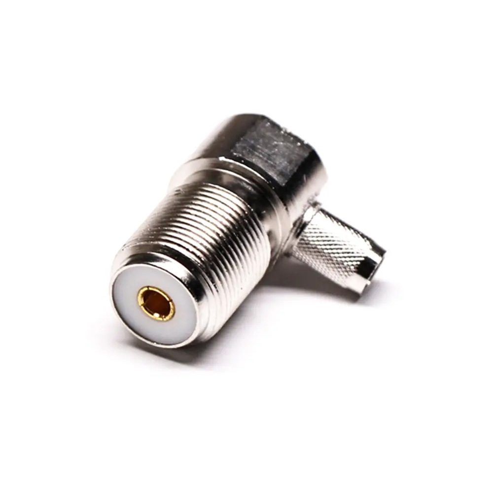
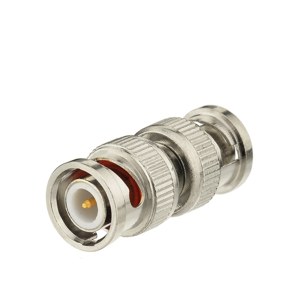
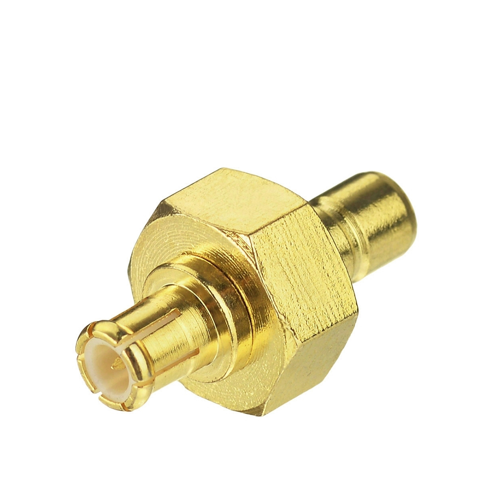
With the continuous advancement of technology, many manufacturers have introduced various finished antennas to reduce R&D cycles. However, improper antenna selection can prevent the desired outcomes, leading to wasted time and costs in troubleshooting and debugging. To avoid such losses, we will present several common antenna types for your reference.
Common Antenna Types
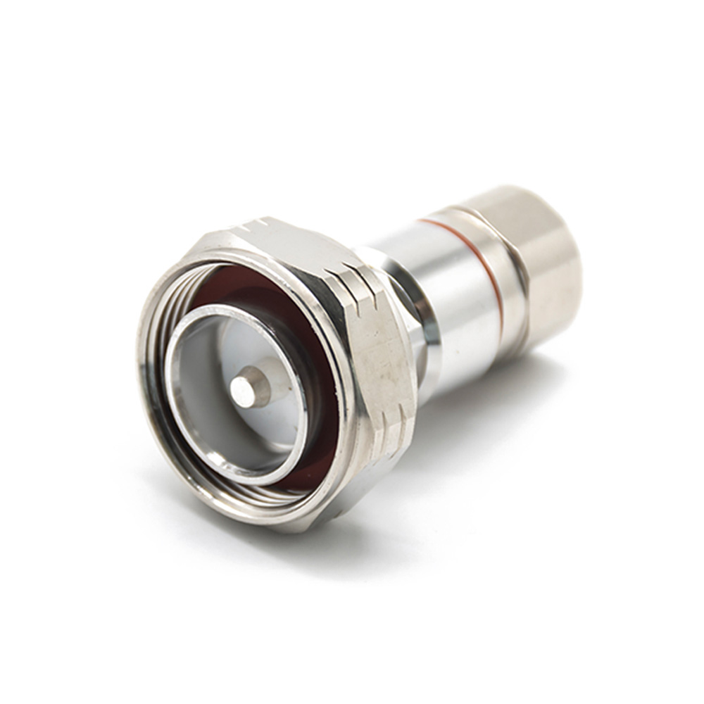
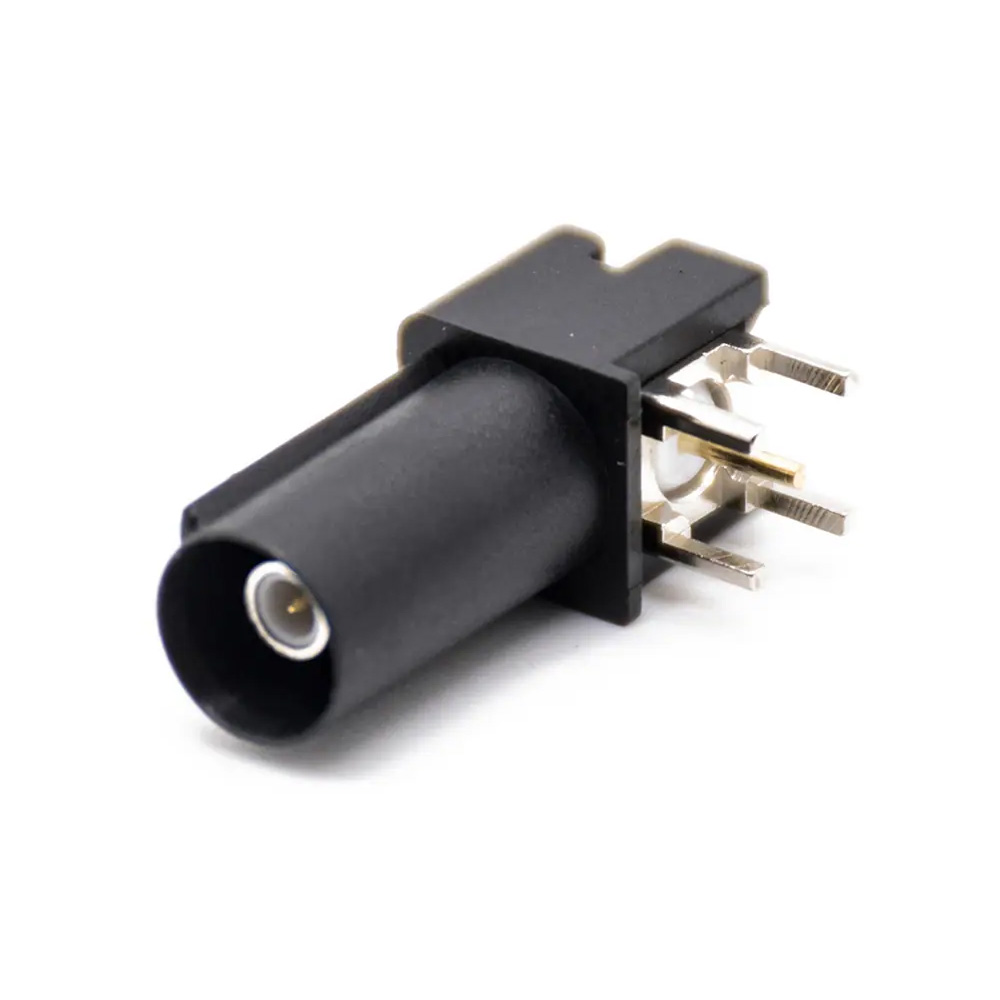
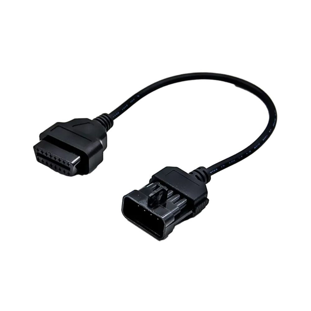
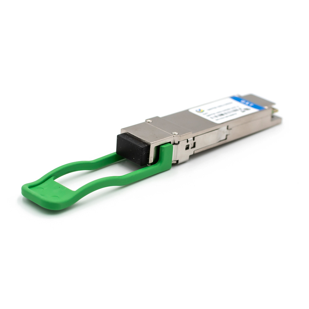
On-board PCB Type Antenna: This antenna is etched through PCB processing, offering low-cost production and mass production suitability. Its performance may be somewhat limited, but its adjustability makes it ideal for Bluetooth, WiFi, and other wireless communication modules, meeting basic communication needs.
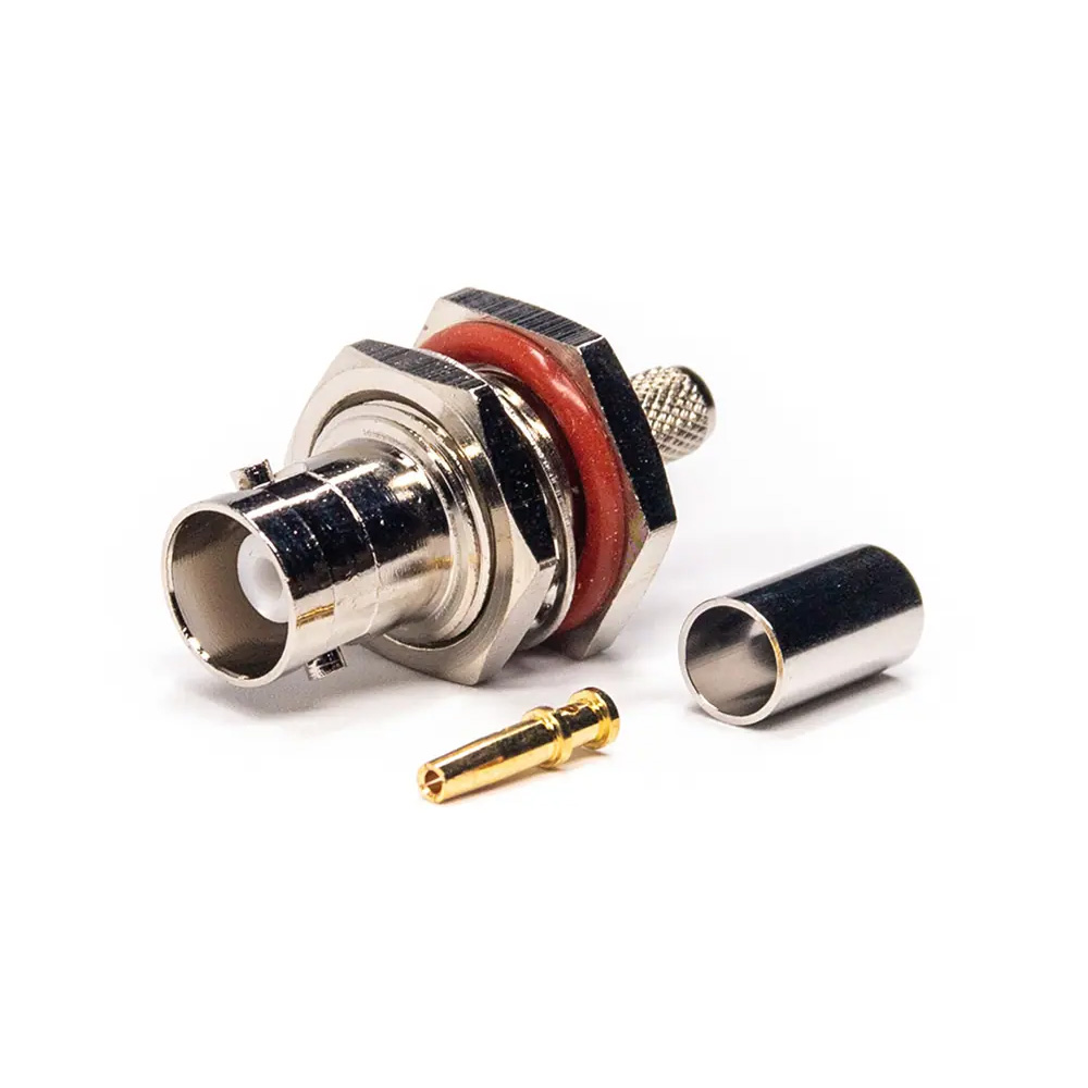
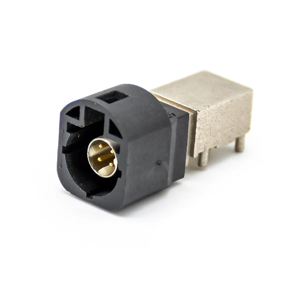
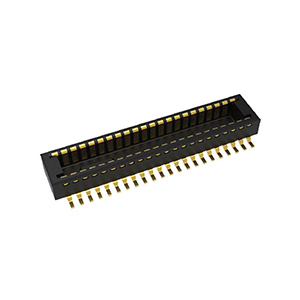
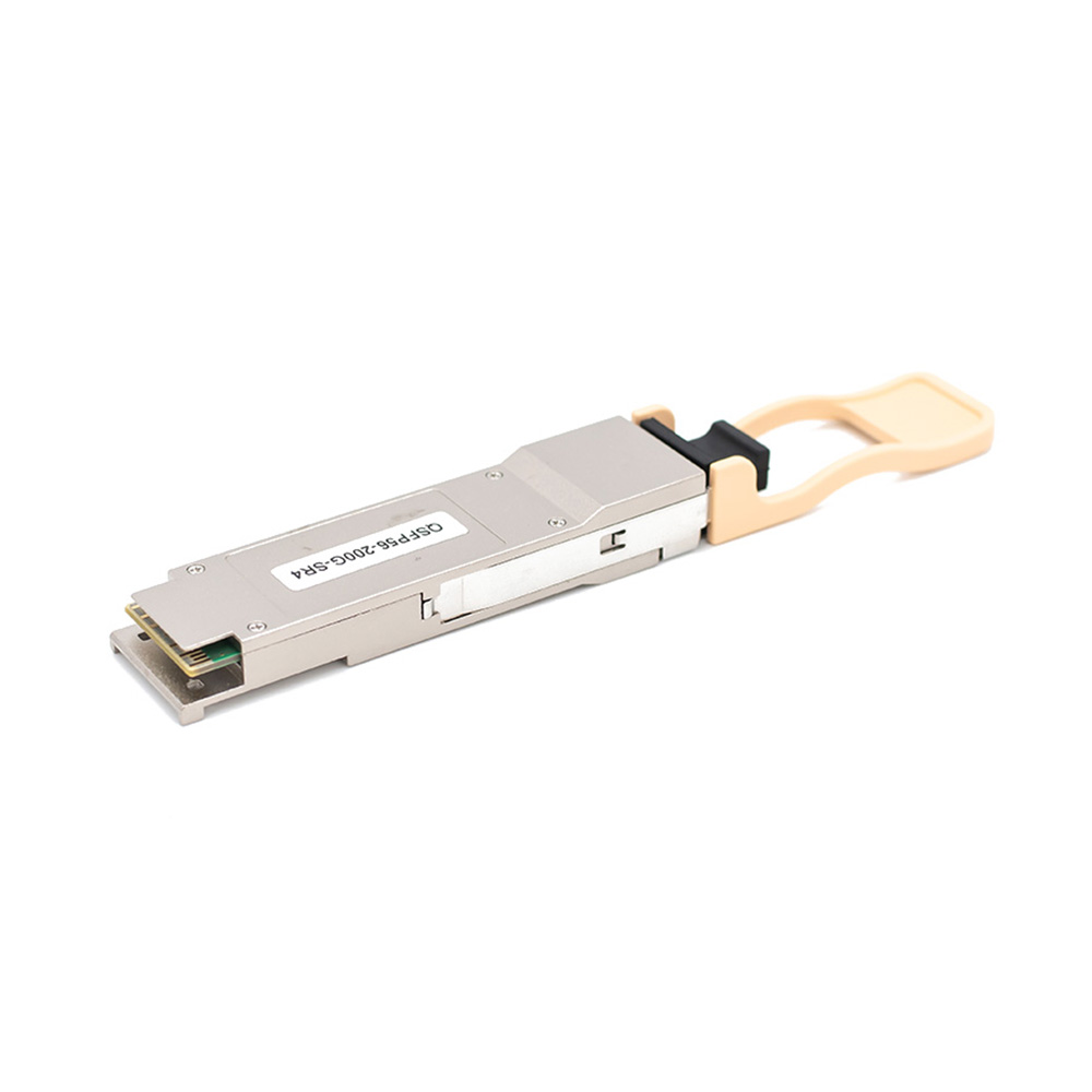
SMT Patch Antenna: This common ceramic antenna has a small footprint and high integration, making it easy to replace. It is particularly suitable for products with limited space. While it has a slightly higher cost and smaller bandwidth, it remains an excellent choice for compact designs.
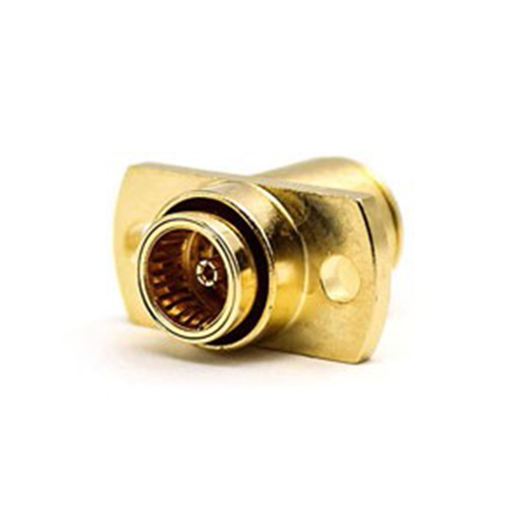
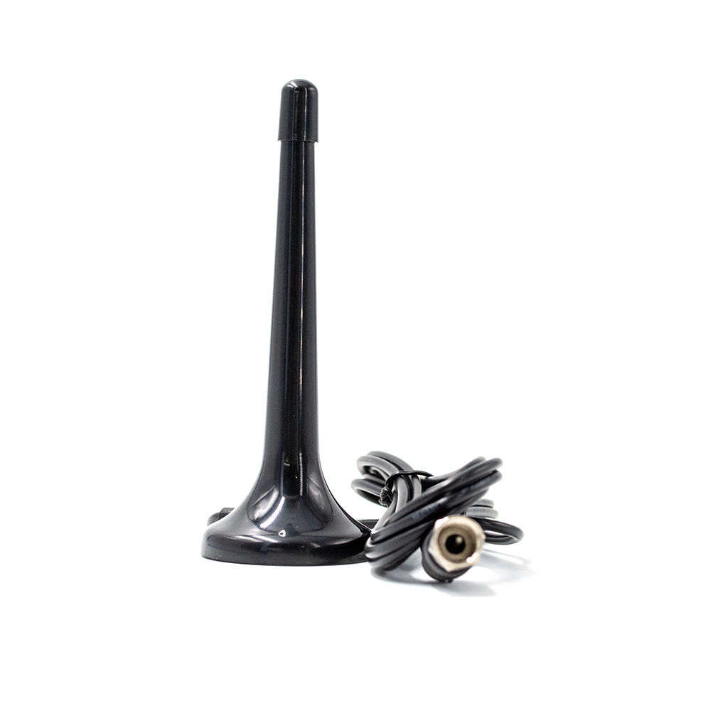
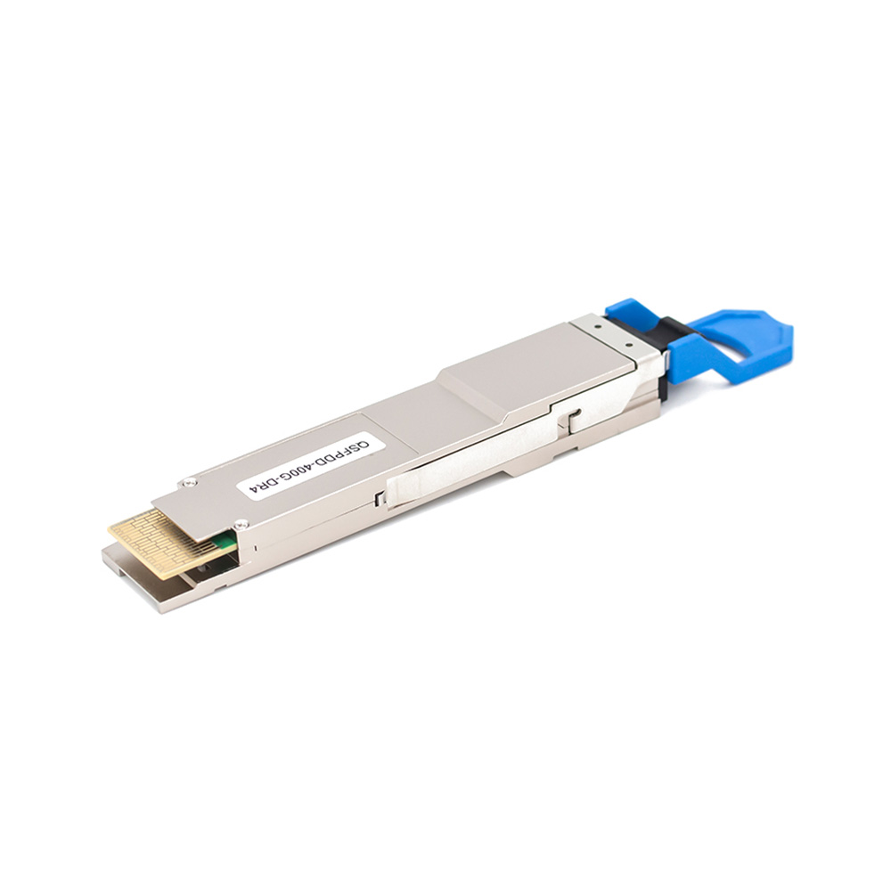
External Stick Antenna: External stick antennas provide high performance, easy installation, and high gain. They are ideal for various terminal devices, especially in application scenarios requiring strong signal strength and stability.
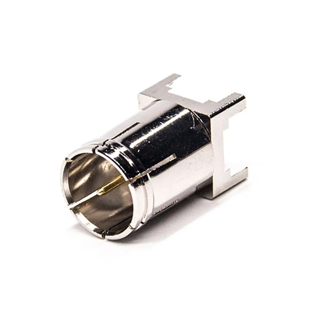
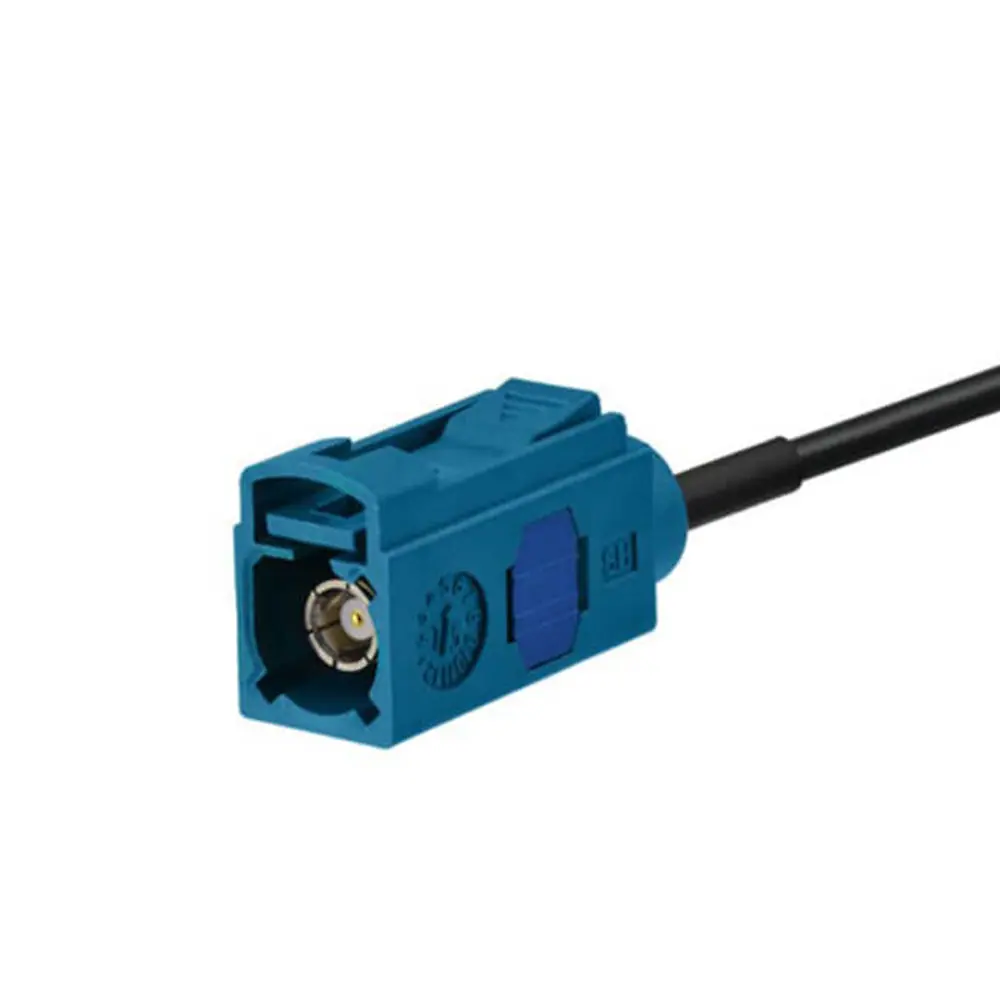
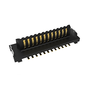
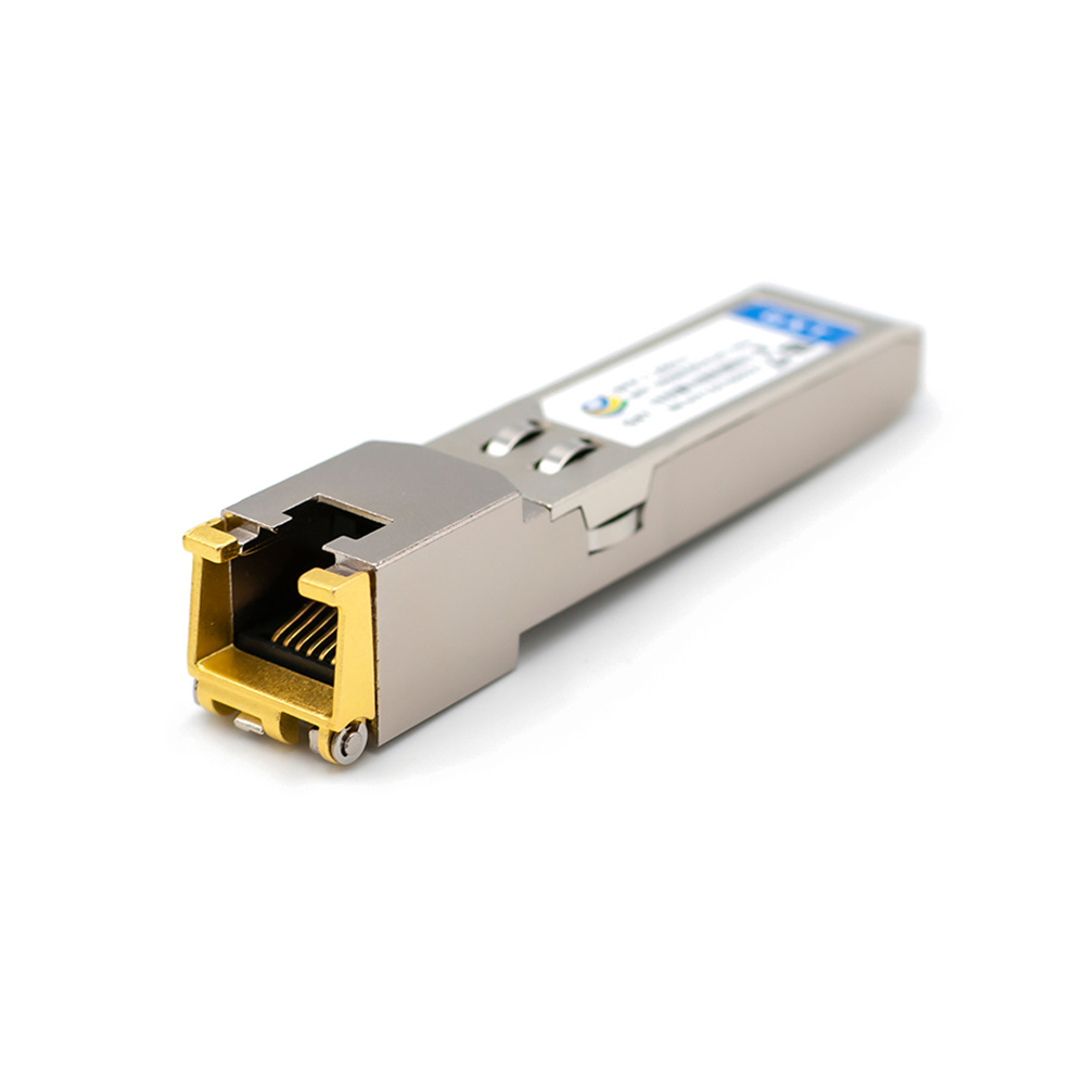
FPC Antenna: FPC antennas connect via a feed line, offering flexible installation and high gain. They are typically affixed to non-metallic enclosures with adhesive backing, making them suitable for high-performance products with sufficient shell space. Their main advantage is flexibility, ensuring excellent signal transmission without space constraints.
| Type | Product Pictures | Specificities | Applications |
| On-Board PCB Antenna |  | Low cost, but limited performance, good tunability | Integrated RF modules such as WiFi, Bluetooth modules |
| SMT Ceramic Antenna |  | Small footprint, highly integrated and easy to replace | For high-volume embedded wireless modules |
| External Stick Antenna |  | Good performance, no need for commissioning, easy to replace, high gain | Customer terminal equipment |
| FPC Antenna |  | Freedom of installation and high gain | Customer terminal equipment |
Antenna Selection
The key performance indicators for antennas include frequency range, VSWR, antenna gain, polarization method, and impedance. Select the frequency range based on your needs, keep VSWR below 1.5 for optimal signal transmission efficiency, and ensure antenna gain supports your desired transmission distance. Choose the polarization mode (linear or circular) based on your application, and match the impedance to the wireless module’s output, usually 50 ohms.
Pay special attention to the VSWR parameter. Use a network analyzer to test the VSWR after purchasing the antenna to ensure it meets performance requirements.
| VSWR | VSWR (dB) | Return Loss (dB) | Trans. Loss (dB) | Volt. Refl. Coeff | Power Trans. (%) | Power Refl. (%) |
| 1.0 | .0 | ∞ | .000 | .00 | 100 | .0 |
| 1.1 | .8 | 26.4 | .010 | .05 | 99.8 | .2 |
| 1.2 | 1.6 | 20.8 | .036 | .09 | 99.2 | .8 |
| 1.3 | 2.3 | 17.7 | .075 | .13 | 98.3 | 1.7 |
| 1.4 | 2.9 | 15.6 | .122 | .17 | 97.3 | 2.8 |
| 1.5 | 3.5 | 14 | .177 | .2 | 96 | 4 |
| 1.6 | 4.1 | 12.7 | .238 | .23 | 94.7 | 5.3 |
| 1.7 | 4.6 | 11.7 | .302 | .26 | 93.3 | 6.7 |
| 1.8 | 5.1 | 10.9 | .37 | .29 | 91.8 | 8.2 |
| 1.9 | 5.6 | 10.2 | .440 | .31 | 90.4 | 9.6 |
| 2 | 6 | 9.5 | .512 | .33 | 88.9 | 11.1 |
| 2.5 | 8 | 7.4 | .881 | .43 | 81.6 | 18.4 |
| 3 | 9.5 | 6 | 1.249 | .5 | 75 | 25 |
From the table, you can see that when VSWR is 1.5, the theoretical transmission power is 96%. But at VSWR 2, transmission power drops to only 88.9%. Though some antennas have a VSWR below 2, it is always better to choose an antenna with a VSWR of under 1.5 for optimal transmission power.
Antenna Directionality
Antennas are directional, meaning their ability to radiate or receive signals varies based on direction. Directionality is measured by a directional diagram. The figure below shows the directionality of an antenna with a frequency range of 2400 MHz to 2500 MHz.

When placed vertically, the deepest red area indicates the direction of maximum radiation or reception. To optimize signal quality, install the antenna toward this red area. Also, avoid placing metal objects in the transmission or reception direction, as they can shield the signal.
Some antennas include two-dimensional directional diagrams (H-Plane and E-Plane), as shown below.

Importance of Directionality in Wireless Communication
Antenna directionality is crucial when testing wireless modules. In an unobstructed space, aligning the antenna with its strongest radiation direction maximizes communication range. Improper antenna installation can shorten communication distance or prevent communication entirely.
Engineers often face weak signals, communication distances falling short of expectations, or high packet loss rates. If the wireless module is functioning correctly, first check the antenna’s performance. Ensure the antenna points toward its strongest signal direction during testing for reliable and accurate results.
Antenna Circuit Design
During schematic design, reserve a π-type network between the antenna and the RF output pins of the module. The antenna impedance is influenced by the PCB layout, placement, and surrounding metal. This network ensures the impedance matches 50 ohms if there is a significant deviation.
X1, X2, and X3 are reactance elements. If the antenna impedance is standard (50 ohms), X2 and X3 can remain unsoldered, and X1 should be connected to a 220pF capacitor or a 0-ohm resistor. Keep these components close to the module’s RF output pin and ensure short, straight transmission lines. Avoid placing ground traces within a 1.5mm radius of the matching components to minimize parasitic effects.

In PCB design, since most antennas and modules have a 50-ohm impedance, use 50-ohm microstrip lines between the RF output pins and the antenna to reduce energy reflection. Commonly used FR4 material (dielectric constant 4.2-4.6) provides good performance. The microstrip line width should be approximately 2.2 times the distance to the reference layer to achieve a 50-ohm characteristic impedance.
For precise design, use microstrip line impedance control tools (e.g., ADS, txline, etc.) to optimize the design, then fine-tune it through testing. As shown in the figure, ensure the ground layer under the microstrip line remains intact, and add multiple grounding vias to maintain signal integrity and ground stability.

Effects of Metals on Antennas
If a metal object is near the antenna, it can reflect electromagnetic waves, reducing the antenna’s effective working space, increasing loss resistance, and lowering radiation efficiency. This leads to degraded antenna performance. When installing the antenna, follow these guidelines:
- a: Keep the antenna at least 5mm away from the battery.
- b: Maintain a minimum distance of 4mm between the antenna and the shielding shell.
- c: If an enclosure is needed, avoid using metal-containing spray paint or coatings on the enclosure surface.
By following these simple design tips, you can significantly improve wireless product antenna performance. Have you mastered them?

